To complete your Mechanical Engineering degree at Purdue, you need to take a senior design class. Each team has the option to do an industry
or research sponsored project, or create a project of their own. Our team decided we wanted to create something of our own, as we believed that
finding the problems was just as important as solving them, and didn't want to be handed a project by someone else. One of my teammates had
the idea of making a robot that could automatically inspect power lines, and with the recent Maui and Marshall fires, our team thought that it
would be an interesting and impactful project.
We started our work on this project by performing a deep dive on prior art. We found many sources to draw inspiration from, decide what we like,
and decide what we think we could improve upon. Another very important thing we did near the beginning of the project was to define our scope.
The main things we declared as out of scope were any effects from the emfs caused by the high voltage of the power lines, the actual data collection
on the power lines, and any aspects of charging the robot while it was operating on a power line. We knew that in one semester, we weren't going to
solve every issue in this field. Our main goal for this project was the the traversal of power lines. The use of obstacle detection and sensors has
been done before, but if we could build something that had the strength and maneuverability to get around obstacles such as insulators and aircraft
marker balls, then we would be making a step towards finding a complete solution.
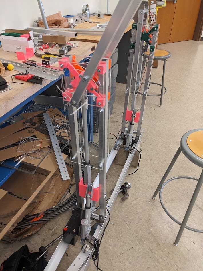
We settled on a design that consisted of three arms attached to a main chassis at the bottom. The robot would move in one of two ways. Either,
it would use drive wheels to translate forward or backward

(Close up of one of the arms in halfway extended position)
along the line, or, when it approached an obstacle, it would take one arm off of the
line and reach around to the other side of the obstacle. The way that it would perform this action was with two types of movement. First, the arm
would be lifted off the line by a linear actuator, supporting itself on the line with the other two arms. Next, the arm would rotate forward
with the help of another linear actuator. The arm would then retract, grabbing back on to the line. The robot would then drive forward, and repeat
the process two more times for the other arms.
One of our philosophies when working on this project was to test early and test often. This allowed us to spot issues ahead of time, not waste
time working on something that didn't function, and greatly improved our troubleshooting ability when integrating components together. This also
included the making of multiple preliminary prototypes, some made out of cardboard or scrap metal found in the machine shop.
Once we agreed upon a design and our prototypes proved promising, it was time to construct our final version of the robot. We used a variety of
machines (lathe, manual mill, laser cutter) and materials (aluminum, steel, acrylic, PLA) to accomplish this. Throughout the process, we kept an
up-to-date digital twin of our robot in SolidWorks. After many minor adjustments and validation tests, the robot was finally ready to attempt to
move around obstacles.
There was one part of the robot that we consistently had the most trouble working with, and that was the track. When the arms of the robot would extend
and retract, there was a set path that we wanted the arms to take. The main function of this path was to rotate the arm away from and back towards the
line, allowing it to move around larger obstacles that stuck out from the line, such as aircraft marker balls. The first issue with the track was its
design. At first, we weren't even sure that this idea would work. Initially, we just threw together a design and see if it worked the way we wanted it
to. It worked remarkably well, so next we actually did some math to get some requirements for how far the track had to extend, and what angles we needed
to get around the obstacles. That design seemed to work well, except when the acrylic cracked. Our third and final iteration used the requirements of
the previous design, but was changed slightly to be slightly smoother and avoid stress concentrations.
The other issue with the track was getting the pins to travel through it effectively. We wanted washers on either side of the track to prevent rotation
into and out of the track, but these washers increased the friction and would sometimes get stuck, causing the acrylic to crack if we didn't stop it fast
enough. The main solution to this was to turn down the bolt inside with a lathe and slide a bearing onto the shaft. This reduced our friction significantly
on certain sections of the track. We also messed with the spacing between the track and the washers a lot in order to find the perfect medium between
providing support and preventing them from getting stuck while in motion.
Another issue that took some time to figure out was our center of mass causing the middle arm to bear the majority of the load of the robot after we
took one arm off the line. Our initial solution to this was to have a 10lb dumbbell attached to a lead screw at the bottom of the chassis that could be
moved back and forth to change the center of mass of our robot. However, we quickly came to realize that this system was quite clunky and would cause
the robot to traverse over obstacles even slower than it already was. Thankfully, there was a really simple solution. Before the first arm was taken
off the line, we could rotate the middle arm forward. This increased the horizontal distance between the center of mass and the contact point of the
middle arm, which distributed the load more evenly between the second and third arms.
The last major issue that we had to figure out how to resolve was excess torsion forces on the chassis. Whenever one of the arms would lift off of
the line, the chassis would twist in a way that could potentially cause problems in the future. We tried to make cross braces for the chassis to
stop the rotation, but it didn't solve the issue. We eventually decided to switch to a chassis made out of steel. This ended up solving multiple
issues in one. The steel chassis was much stiffer than the aluminum chassis, so it eliminated the torsion problem. It also weighed a lot more,
bringing our center of mass lower on the robot. We were also able to easily suspend more mass off to one side of the robot, ensuring greater stability
while on the line.

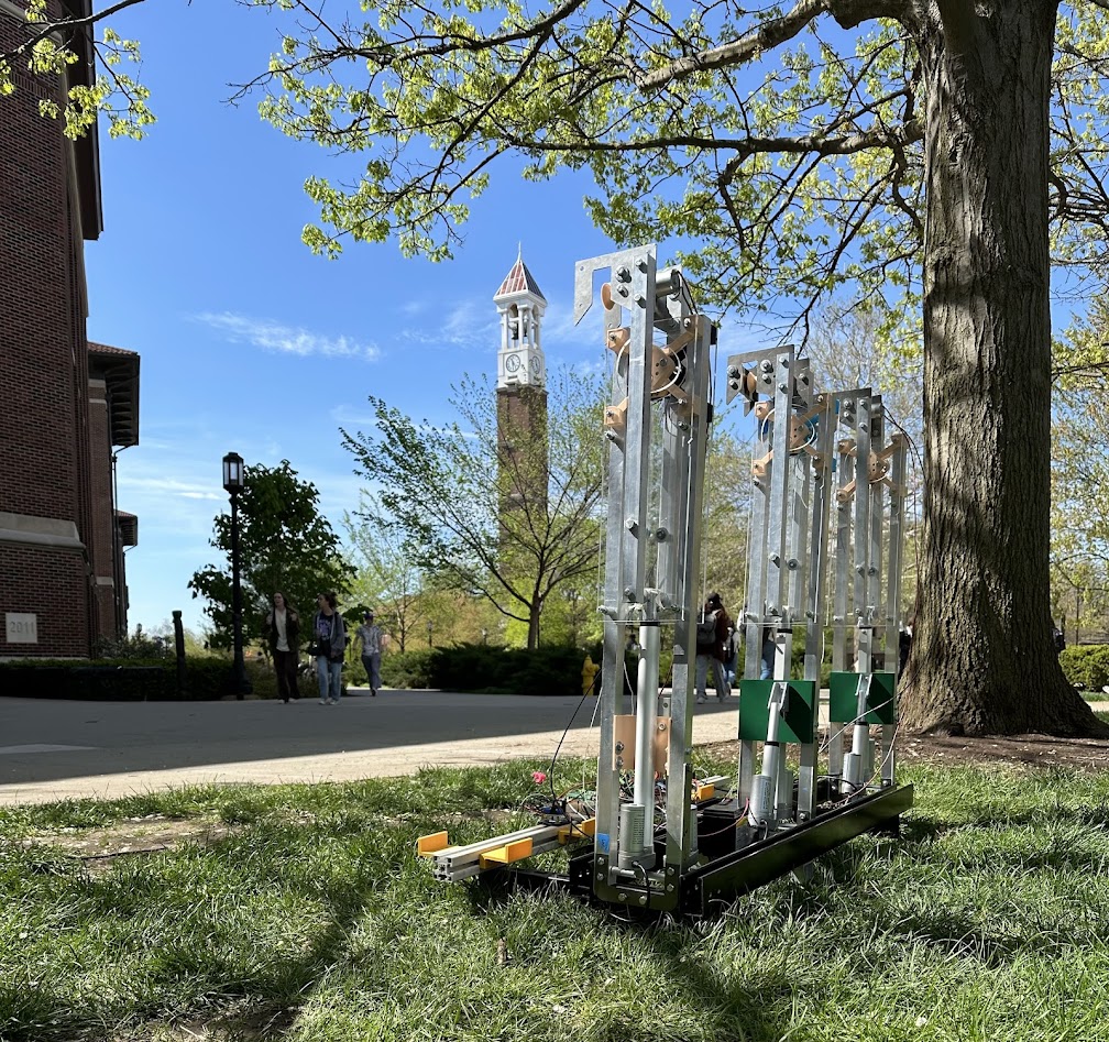
(Robot by the bell tower after we finished testing)
This project was a great success! The robot was able to move around the obstacles that we decided to test. I really enjoyed getting to work on
this
project as well as this team. I think we got along great, and I learned a ton about larger scale projects and teamwork. I hope that I can get to
do something with the project in the future. If you'd like to see videos of the robot and our tests,
here is a link to a YouTube playlist.
 (Close up of one of the arms in halfway extended position)
 (Robot by the bell tower after we finished testing)