This project was created with the help of two teammates for the final project of our controls 2 lab section. We were tasked to create a
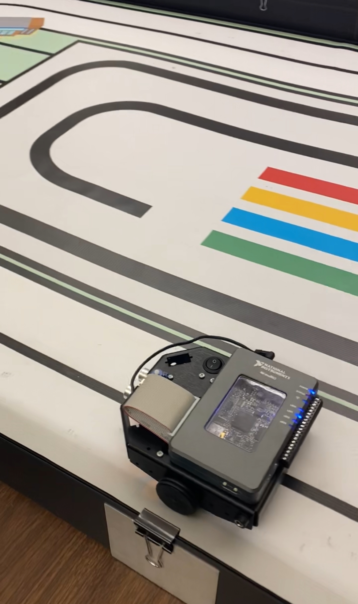
robot that was able to follow a black line along a preset track for one lap, and then automatically switch to a "herding" behavior that
would maintain a set distance from a moving object. Since the physical construction of the robot was conducted earlier in the semester
and was completed by following a video tutorial, it will not be the focus of this project page.
The logic for the robot was constructed using an NI LabVIEW VI, along with some sub VI's. A good portion of the block diagrams were given to
us to use as a starting point, as we had made similar features in previous labs. These features included reading and outputting analog data
from the myRIO device and scaling encoder counts, and were trivial in comparison to the rest of the project. The majority of the effort that
was put into this project went to developing a finite state machine for each behavior, and fine-tuning the controller values. Our finite state
machines were made using a switch statement inside a simulation loop in the VI. This way, the robot would move according to the parameters
set by the state that it was in, and then transition to the next state by using the conditions in the switch statement.
The finite state machine for the line follower behavior consisted of four states: the starting state,
straight, turn left, and turn right. In the starting state, both wheel velocities were set to zero. The
robot would remain in the starting state until the Go button was pressed on the front panel, in which it would

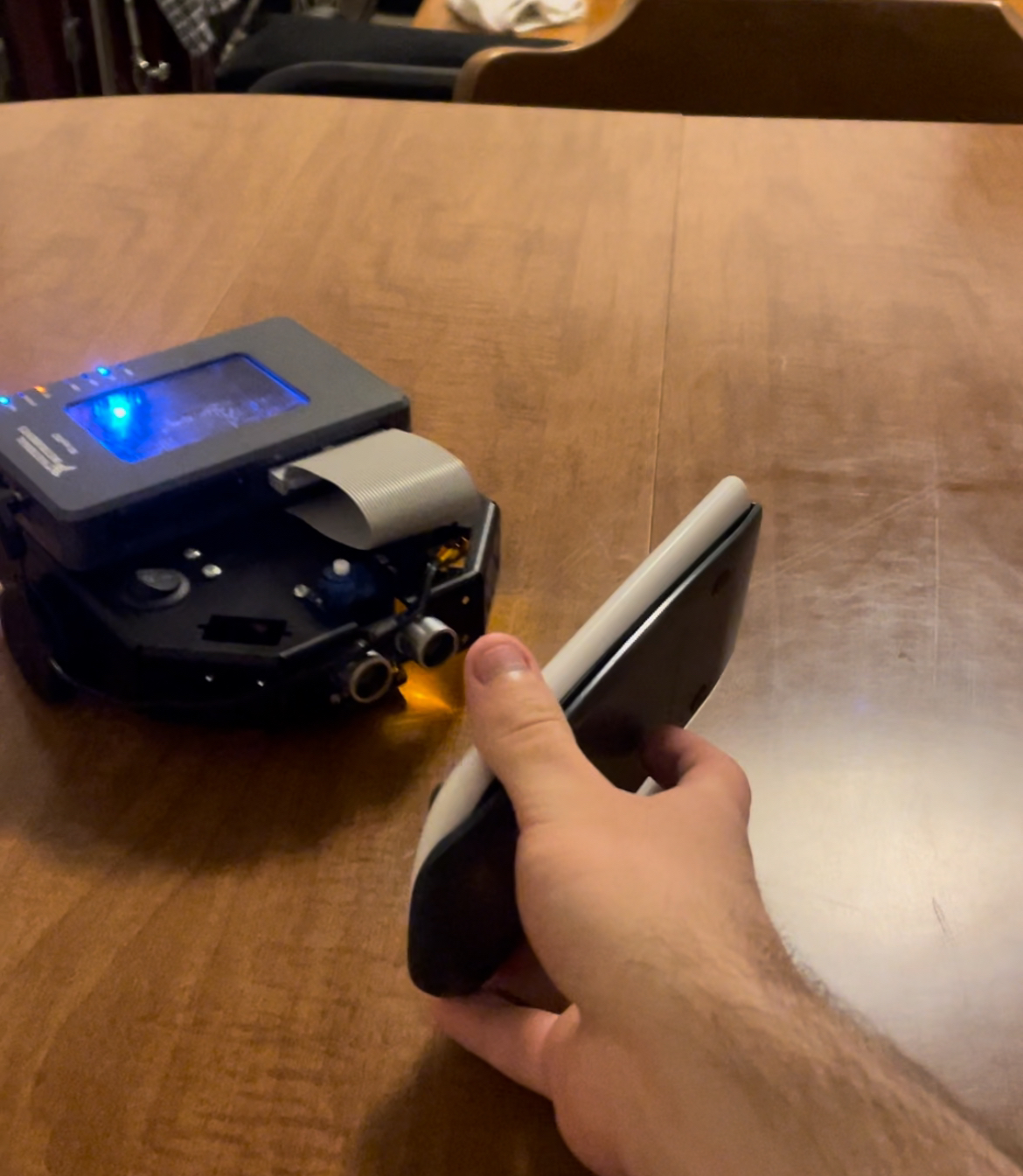
(Testing of the herding behavior using a calculator)
move to the straight state. In the straight state, both wheel velocities were set to 10. In the
turn left state, the right wheel velocity was set to 10, and the left wheel velocity was set to 0. For
the turn right state, the right wheel velocity was set to 0, and the left wheel velocity was set to 10.
The robot would only enter the starting state just after the VI was run, and would exit as soon as
the Go button was pressed. The logic for switching between states was the same for the other three
states. If only the left sensor or only the left two sensors were turned on, then the robot would enter
the turn right state. If only the right sensor or only the right two sensors were turned on, then the
robot would enter the turn left state. Otherwise, the robot would return to the straight state.
The finite state machine for the herding behavior only had three states: stay, forward, and reverse.
In the stay state, both wheel velocities were set to 0. In the forward state, both wheel velocities
were set to 10. In the reverse state, both wheel velocities were set to -10. The logic used to switch
between states was straightforward. If the ultrasonic sensors detected that an object was more than
9.5 inches away, the robot would enter the forward state. If an object was detected to be less than 8.5
inches away, the robot would enter the reverse state. An object being detected in between 9.5 and 8.5
inches would cause the robot to enter the stay state. There needs to be some range of values, otherwise
the robot would constantly switch between the forward and reverse state when an object was placed
approximately 9 inches away.
One of the big issues my group encountered while doing this project was finding the best values for our PID controller. Our initial calculations
seemed to be correct according to theory, but our response when testing was not at all what we wanted. The robot would shake violently in place whenever the speed
for each wheel was set to zero. We found that the reason for this was the physical limitations of the robot itself. Some of the components for
the robot were not the highest quality, so our already large amount of noise was being amplified dramatically by our derivative controller
component. After conducting a lot of trial and error testing, we found that simply eliminating the derivative control was the best option.
The difference in dead band ranges between our left and right wheel was significant. This caused some issues because when our robot was set to move straight,
the difference in velocities of the wheels caused the robot to turn slightly to the right. While our robot could still complete the track following the line,
the time it took to accomplish this was significantly increased due to the robot having to adjust itself on the straightaways. Our group tried to fix this
issue by setting the velocity of the left wheel to be lower than the right wheel. This had noticeable positive effects in the behavior of our robot on the
straight sections of the track, but we were unable to eliminate the error completely.

(Robot doing its demonstration on the provided track)
Since a very large percentage of my interactions with controller design had been theoretical, it was good to have some exposure to designing a controller under
real world conditions. These differences had tangible impacts, such as my group making the decision to eliminate the derivative portion of the controller entirely.
While that gave us overall a better result because of the reduction in noise, it increased the settling time, causing the robot to have a slower response. This
project illustrates that sometimes the theory doesn't translate directly into the real world, but by understanding how each portion of the controller impacts
the final result, we were able to make adjustments to achieve an acceptable behavior.
 (Testing of the herding behavior using a calculator)
 (Robot doing its demonstration on the provided track)